Calcium Chloride Plant
Among many uses, Calcium Chloride is increasingly being used in winter as defrost on roads and highways.
The calcium chloride may be derived as a byproduct of the Solvay process sodium carbonate that had the big advantage of producing soda on low cost, used for the production of detergents, or is obtained starting from ‘electrolysis of sodium chloride and then follow with the reaction between calcium carbonate and hydrochloric acid:
2 NaCl + 2 H2O → Cl2 + H2 + 2 NaOH
CaCO3 + 2 HCl → CaCl2 + H2O + CO2
This publication deals the design and construction “epc”, of a calcium chloride plant starting from this second reaction, and in particular describes the first phases of the project like the feasibility study and “Front End”.
The plant has been commissioned by a private company and Eastern European and the design covered the whole of the factory: the operational and executive offices; the storage of raw materials and finished products, the filling lines and all the utilities.
The work was conducted by an engineering company as main contractor in partnership with other engineering companies that own the licenses as “e,p”.
Finished products output:
calcium chloride* 2 H2O 35,000 Ton / Year
caustic soda 32% 50,000 Ton / Year
18% sodium hypochlorite 11,000 Ton / Year
Raw materials input :
salt NaCl 24,000 Ton / Year
calcium carbonate 26,000 Ton / Year
HCl 32% 45,000 Ton / Year
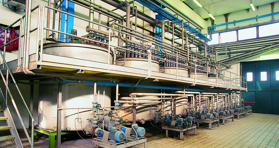
GENERAL DESCRIPTION OF CALCIUM CHLORIDE PLANT
The main sections of the plant are the following:
2) Hydrogen synthesis
3) Hydrochloric acid synthesis
Electrolysis process (licence by an engineering company)
The electrolyte feeding the electrolyzer is an aqueous solution of sodium chloride 30% c.a. NaCl The saturated brine is pumped to the reactors, mechanically agitated, where it is mixed with chemicals to precipitate the impurities (magnesium, calcium and sulphates).
Then the brine is fed to the clarifier and a flocculant solution is added; the clarified brine is pumped to the brine filters.
Filtered brine is pumped through the carbon filter to remove the excess hydrogen peroxide that is used for dechlorination.
Before reaching the electrolysis, the filtered brine undergoes the secondary process to reduce the Ca and Mg.
A single element comprises the anode and cathode and a semipermeable membrane,
The anode is made from titanium whereas the cathode is made from nickel.
The current is conducted from cell to cell element via Ni-Ni contacts.
Pure brine enters the anode compartments where chlorine is generated at the titanium anodes. Anode and cathode compartment is isolated by a membrane which is hydraulically impermeable. It only allows individual diffusion of Na+-ions and a certain quantity of water into the cathode chamber . Hydrogen and OH- ions are generated at the cathodes.
Hydrogen synthesis (licence by an engineering company)
The hydrogen coming from the electrolysis room, saturated with water vapour, flows through a H2 washing cooling tower where the gas is cooled so that most of its water vapour is condensed.
Hydrochloric acid synthesis (licence by an engineering company)
The Hydrochloric Acid plant consists of a furnace, an absorber and a scrubber column.
Chlorine and hydrogen are fed to the furnace forming HCl.
The demineralized water required for absorption flows counter-current to the gas stream from the scrubber column to the absorber. The produced 32% hydrochloric acid leaves the falling film absorber.
Calcium Chloride plant- Process Description
This unit is designed to produce 35,000 metric tons per year of calcium chloride dihydrate with a purity of 99%.
The raw materials fed to the unit are :
Hydrochloric acid at 33% coming from a chlorine conversion unit downstream a electrolytic caustic soda production plant . We assume that demi water is used foe gaseous acid absorption.
Limestone at 99.5 purity level grinded at 200 mesh
Demi water
Other required chemicals are:
Lime milk 10% of concentration
The following utilities are available:
Saturated steam at 4 barg minimum
Cooling water at 28°C
Instrument air at 5 barg min and dew point at -20°C
LV Electric power 380 V 3 ph 50 Hz
LPG liquid fuel (LHV 46,1 KJ / g)
The unit is producing, as by product, about 1400 kg/h of carbon dioxide at 95% saturated of water at ambient temperature. The carbon dioxide could be compressed and dried , but no facilities are provided in this proposal for this recovery.
Part of the evaporated water from reaction liquor is recovered as soft water to be reused inside the factoryThe product is available as dry powder ready to be stored (storage and packing not included in this proposal)
The gaseous emissions of the unit are :
The mentioned concentrate carbon dioxide if not compressed treated and reused.
The dryer emissions (800 kg/h of CO2)
There are not pollutant liquid emissions.
Design basis of Calcium Chloride Plant
The mechanical design is oriented to skid mounted equipment.
The unit is designed for continuous operation, with a service factor of 7500 h/y.
The unit is designed for centralized operation from control room in this proposal we suppose the DCS supplied by others. The chemicals preparation and daily tank handling are manual operations
It is foreseen to provide a safety system installed on a dedicated PLC in the control room.
It is foreseen to provide an electrical panel in the mcc room fed by LV distribution
Raw material feeding of Calcium Chloride Plant
The hydrochloric acid is fed to the reactors from a surge tank by a centrifugal pump, the flow is controlled by a flow control loop. The surge tank has a capacity of 50 m3 (12 hour at full capacity)
The limestone, already grinded at suitable size, is fed from a storage vessel to a temporary hopper by a suitable conveyor. The limestone storage is foreseen of 50 m3 of capacity. A rotary vane valve supply the limestone to the first reactor. The feeding rate is kept at constant ratio with the acid flow.
Reaction of Calcium Chloride Dihydrate
In this section the reaction between acid and limestone take place in liquid phase with a large development of gaseous carbon dioxide. The gas is routed out from the reactors by a closed vent system while the slurry (aqueous acid solution and limestone) overflows from first reactor to the second reactors, where the process is completed.
The reaction produces also water and calcium chloride accordingly with the following reaction model:
2 HCl + CaCO3 = Ca Cl2 + H2O + CO2 + heat
The produced heat is more than one million of kjoule and must be removed in order to avoid a massive evaporation of acid, this function is provide by two heat exchangers (one for each reactor) cooled with water. Two recirculation pumps provide the necessary flow to the external cooler. Each reactor is provided with a stirrer in order to guarantee the intimate contact of the dishomogeneous reacting phases.
In each reactor the limestone concentration is kept higher than the stechiometric ratio, in order to promote the total consumption of the acid and reduction of concentration in the reactors. The acid water from the gas scrubber is recycled to the reactors.
Then the liquid phase leaving the reactors shall be a liquor with about 40% w/w of calcium chloride, with a solid dispersed phase of limestone. This slurry is fed with a pump to an hydrocyclon where the limestone is separated and recycled to the reactors.
The hydrocyclone overflow (almost clear liquor) is fed to neutralization section.
Carbon dioxide scrubbing section of Calcium Chloride Plant
The reactor vented carbon dioxide washed in a packed column with soft water from concentration section in order to eliminate the evaporated acid gas and reduce the associated water vapor . The washing water is recirculated with a pump. The bleeding of the closed circuit is sent to the first reactor.
Liquor of Calcium Chloride Plant : neutralization and clarification
The liquor of Calcium Chloride Plant leaving the second reactor is fed by gravity to the neutralization tank where the pH correction takes place adding a suspension at 10% of lime milk.. The neutralization tank is provided with a stirrer and with an automatic pH control system. At neutralization tank outlet the liquor is added with a flocculent and discharged by gravity in a clarifier In this equipment the residual suspended solids are settled. The overflow is recovered in a buffer tank.The under is recycled to the first reactor by volumetric (mono ) pump,
The CaCl2 solution at about 40% is concentrated up to 55-58% in a triple effect evaporator.
The last effect, operating at about 0,3 is connected with a liquid ring vacuum pump system.
The water vapor is condensed and received in a barometric receiver. Part of condensed water is reused in the scrubbing sector, the remaining is available as soft water for the factory uses.
Calcium Chloride Plant- Product drying
The liquor stored in the buffer tank is fed by a centrifugal pump a steam heater and then to a spray dryer. The heat necessary to evaporate the water is given by a natural gas burner system providing the hot air to the dryer. The product, in form of powder, is recovered on the equipment bottom. The temperature control in the dryer is a crucial parameter in order to obtain the dehydrate crystallization form. The powder is discharged from the dryer in a service bin suitable for a pneumatic transport in dense phase and high pressure in order to be sent to a storage vessel. The
exhaust air is filtered in a bag filter the entrained powder returns to the dryer and the exhaust air is sucked up by an end blower
 D5 Creation